- 您现在的位置:买卖IC网 > Sheet目录1999 > ID82C54 (Intersil)IC OSC PROG TIMER 8MHZ 24DIP
20
82C54
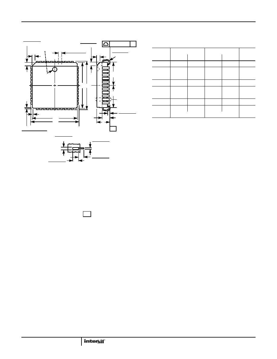
Plastic Leaded Chip Carrier Packages (PLCC)
NOTES:
1. Controlling dimension: INCH. Converted millimeter dimensions are
not necessarily exact.
2. Dimensions and tolerancing per ANSI Y14.5M-1982.
3. Dimensions D1 and E1 do not include mold protrusions. Allowable
mold protrusion is 0.010 inch (0.25mm) per side. Dimensions D1
and E1 include mold mismatch and are measured at the extreme
material condition at the body parting line.
4. To be measured at seating plane
contact point.
5. Centerline to be determined where center leads exit plastic body.
6. “N” is the number of terminal positions.
-C-
A1
A
SEATING
PLANE
0.020 (0.51)
MIN
VIEW “A”
D2/E2
0.025 (0.64)
0.045 (1.14)
R
0.042 (1.07)
0.056 (1.42)
0.050 (1.27) TP
E
E1
0.042 (1.07)
0.048 (1.22)
PIN (1) IDENTIFIER
C
L
D1
D
0.020 (0.51) MAX
3 PLCS
0.026 (0.66)
0.032 (0.81)
0.045 (1.14)
MIN
0.013 (0.33)
0.021 (0.53)
0.025 (0.64)
MIN
VIEW “A” TYP.
0.004 (0.10)
C
-C-
D2/E2
C
L
N28.45 (JEDEC MS-018AB ISSUE A)
28 LEAD PLASTIC LEADED CHIP CARRIER PACKAGE
SYMBOL
INCHES
MILLIMETERS
NOTES
MIN
MAX
MIN
MAX
A
0.165
0.180
4.20
4.57
-
A1
0.090
0.120
2.29
3.04
-
D
0.485
0.495
12.32
12.57
-
D1
0.450
0.456
11.43
11.58
3
D2
0.191
0.219
4.86
5.56
4, 5
E
0.485
0.495
12.32
12.57
-
E1
0.450
0.456
11.43
11.58
3
E2
0.191
0.219
4.86
5.56
4, 5
N28
28
6
Rev. 2 11/97
发布紧急采购,3分钟左右您将得到回复。
相关PDF资料
IDT2308A-4DCI8
IC CLOCK MULT ZD HI DRV 16-SOIC
IDT2309-1HPGGI
IC CLK BUFFER ZD HI DRV 16-TSSOP
IDT2309A-1HPGG
IC CLK BUFFER ZD HI DRV 16-TSSOP
IDT2309B-1HPGGI
IC CLK BUFFER HIGH DRIVE 16TSSOP
IDT23S05-1HDCGI
IC CLK BUFFER PLL HI DRV 8-SOIC
IDT23S05E-1HDCGI8
IC CLK BUFFER PLL HI DRV 8-SOIC
IDT23S08-1HPGI8
IC CLK MULT PLL HI DRV 16-TSSOP
IDT23S08T-1DC
IC CLK MULT PLL ZD 2.5V 16-SOIC
相关代理商/技术参数
ID82C54/+
制造商:未知厂家 制造商全称:未知厂家 功能描述:Analog Timer Circuit
ID82C54-10
制造商:INTERSIL 制造商全称:Intersil Corporation 功能描述:CMOS Programmable Interval Timer
ID82C54-12
制造商:INTERSIL 制造商全称:Intersil Corporation 功能描述:CMOS Programmable Interval Timer
ID82C55A
功能描述:外围驱动器与原件 - PCI PERIPH PRG-I/O 5V 8MHZ 40CDIP IND RoHS:否 制造商:PLX Technology 工作电源电压: 最大工作温度: 安装风格:SMD/SMT 封装 / 箱体:FCBGA-1156 封装:Tray
ID82C55A/+
制造商:未知厂家 制造商全称:未知厂家 功能描述:Peripheral Interface
ID82C55A-5
制造商:HARRIS 制造商全称:HARRIS 功能描述:CMOS Programmable Peripheral Interface
ID82C59A
功能描述:IC CONTROLLER INTERRUPT 28-DIP RoHS:否 类别:集成电路 (IC) >> 接口 - 控制器 系列:- 标准包装:4,900 系列:- 控制器类型:USB 2.0 控制器 接口:串行 电源电压:3 V ~ 3.6 V 电流 - 电源:135mA 工作温度:0°C ~ 70°C 安装类型:表面贴装 封装/外壳:36-VFQFN 裸露焊盘 供应商设备封装:36-QFN(6x6) 包装:* 其它名称:Q6396337A
ID82C59A
制造商:Intersil Corporation 功能描述:Controller IC Package/Case:28-CDIP